🔧 Newly Uploaded TSBs – Feb./Mar. 2026
Stay ahead of the curve with the latest Technical Service Bulletins (TSBs) added in the past month.
DDTSB is growing again – this time with 216 brand-new TSBs and 141 updates, all based on real hotline cases and real-world diagnostics from workshops across Europe.
Below are three strong and technically relevant examples from the newest uploads.
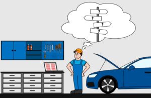
✅ Electric Drive “Turtle Mode” on Volkswagen ID3 / ID4 / ID5: A Diagnostic Trap Many Workshops Miss
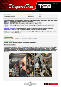
Volkswagen ID3, ID4, and ID5 models from 2019 to 2024 can present an intermittent but serious issue where the electric drive system enters emergency “turtle mode” shortly after driving off. Multiple fault codes are typically stored, often misleading technicians into replacing major components unnecessarily.
Technicians may observe the following:
Vehicle drives normally for 500–1000 meters after standstill… then suddenly, power drops.
The dashboard lights up with an electric drive warning, acceleration is heavily limited, and the vehicle enters turtle mode. What makes this case even more confusing is that the high voltage battery state of charge is perfectly normal.

And here’s where things start to get misleading.
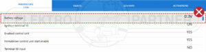
When you run a scan, you are often presented with a long list of fault codes pointing in completely different directions.
If you are not yet familiar with troubleshooting on the MEB platform, you may be surprised by how many fault codes are always stored, many of which can often be ignored. The real challenge is identifying which fault codes are actually relevant to the specific symptom or problem.
Technicians experienced with these vehicles know that it is completely normal for a fully functioning car to have 20 to 30+ stored fault codes spread across more than 50 control units.
This background noise makes it even harder to identify the relevant faults, especially when dealing with an intermittent issue like this.
Typical fault codes seen in these cases include:
B158131 – High Voltage Heating Control Unit – No Signal
P068A00 – ECM/PCM Voltage Relay De-energized Performance Too Early
P0C4700 – Water Pump 1 for High Voltage Battery – Interruption
P1BEF00 – High Voltage Battery Heater Control Module Open Circuit Detection Not Possible
Along with additional faults such as:
B163002, B201200, P068500, P0BBD00, P1CB500, P30C100, U029200, U112100, U112200, U112300, U14FE00, U15BB00, U15FA00, U163F00, U19FE00
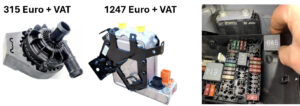
Critical warning before replacing coolant circulation pumps on MEB models. Risk of system damage and possible high voltage warranty issues
Something important to consider before working on the coolant system on these models:
If you decide to replace a circulation pump, as some workshops have done when attempting to fix this issue, you must pay close attention to the bleeding procedure.
The manufacturer requires the use of VAS 531 011.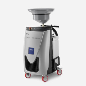
This is not optional guesswork. It is necessary due to the large and complex cooling system in these EVs, including the high voltage battery circuit with a total capacity of around 12 liters.
The procedure starts by opening all valves in the cooling system using a diagnostic tester.
Then:
Coolant must be fully drained. This is done by loosening multiple hoses and allowing gravity to empty the system. The VAS machine monitors the process using an integrated weight system. Once the flow stops, a second stage begins where the machine uses controlled air pressure to push out the remaining coolant. This ensures no coolant is trapped, including inside the high voltage battery cooling channels, without risking damage.
After draining, the system is placed under vacuum. Older equipment could only achieve around 150 mbar absolute pressure, which is not sufficient for these vehicles. The VAS 531 011 pulls the system down to approximately 40 to 80 mbar and monitors whether the vacuum holds. This is critical to ensure no air pockets remain.
Refilling starts using that vacuum, drawing coolant into the system. After this, a guided bleeding procedure must be carried out via the diagnostic tester. During this phase, both electric circulation pumps are activated while the VAS machine maintains approximately 1800 mbar pressure in the reservoir. This ensures all remaining air is removed.
Why does this matter?
Air trapped in a high voltage cooling system is a serious risk. It can lead to overheating of critical EV components. Not always immediately, but when an air pocket moves, it can cause sudden and severe damage. This is not theoretical. It has been seen in real cases.
There is also a warranty aspect to consider.
If the vehicle is still under warranty, documentation is key. It is strongly recommended to note on the invoice that VAS 531 011 was used. Some workshops even take photos of the setup during the process to protect themselves.
Incorrect bleeding does not just risk the repair. It can risk the customer’s warranty.
This is not just about another part that did not fix the issue. It can create an entirely new fault scenario.
So what’s actually going on?
The root cause is surprisingly simple.
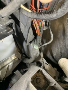
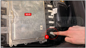
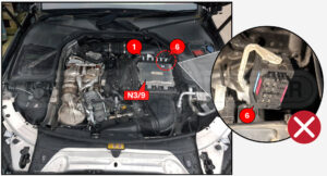
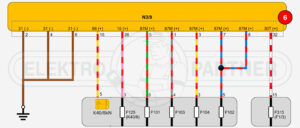
A splice joint near fuse holder B (terminal 30 splice near fuse SB) develops increased resistance due to corrosion or poor connection. This creates an unstable voltage supply to key components like the ABS control unit and main relay.

This is a perfect example of how a small electrical resistance issue can mimic major component failure in modern EV platforms.
If you know where to look, the fix is straightforward.
We have seen an explosion of this problem in our Hotline so frequently, in fact, that we’ve already sent this case out to customers multiple times before it was even officially included in a monthly upload.
That alone says something.
This isn’t a rare or isolated fault anymore. It’s becoming a pattern.
Workshops across different regions are encountering the exact same symptoms, the same misleading fault codes, and in many cases, going through the same unnecessary repair attempts before finding the root cause.
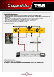
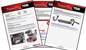
Here is how TSB No. 13071 looks:

 Final Notes
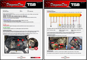
✅Fiat Doblo 1.6 MultiJet – Fault Code P010F Air Mass Incongruence
This is more of a cool story from a workshop on the Shetland Islands, where there was a problem with fault code P010F and an OE recall, but the challenge was that there is no dealership on the island. It turns out the workshop managed to find the problem anyway.
We are also proud to see DDTSB being used in every corner of the world, supporting workshops even in the most remote locations.
Introduction
 Introduction
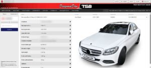
This case is based on a hotline job involving a Fiat Doblo along with other 1.6 MultiJet models such as Alfa Romeo Giulietta, Fiat Punto, and Opel-based variants. The vehicle presented with fault code P010F – air mass/air flow meter incongruence, combined with drivability issues. Interestingly, there was an OE campaign (Bulletin 13263), but without dealer access on the island, proper diagnosis had to be carried out the hard way.
Symptoms
Technicians may experience the following:
– Engine warning light illuminated
– Uneven idle, especially during cold start
– Periodic limp mode activation
– Poor engine performance under load
– Stored fault code P010F
Underlying Cause
The root cause in this case was a heavily sooted intake manifold, restricting proper airflow. This leads to a mismatch between measured and calculated air mass values, triggering fault code P010F.
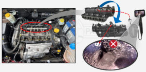
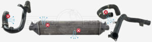
It’s important to understand that the soot build-up is often a secondary issue rather than the primary fault. In many cases, it can be caused by:
– Intake system leaks
– Intercooler damage
– Boost pressure irregularities
Diagnostic Challenges
In many cases, the fault appears intermittent because it takes a certain amount of driving time from when the fault is erased until it is stored again. This can easily lead to the assumption that the issue is intermittent.
In this case, there was also a known OE software-related campaign (Bulletin 13263), which could lead technicians to believe that a software update would resolve the issue.
The outdated software may well have contributed to the soot build-up in the first place. However, performing only a software update will not fix the root problem, as it does nothing to remove the heavy carbon deposits already restricting the intake system.
This is where the trap lies, as following the campaign alone would leave the mechanical restriction untouched, and the fault would likely return.
This is what makes the diagnosis tricky, as the symptoms may point in one direction, while the actual mechanical restriction remains hidden unless it is physically inspected.
In this case, live data comparison played a key role in confirming the fault. By comparing the measured air mass value with the calculated or expected air mass, a clear deviation could be seen under load conditions. This mismatch directly supported the presence of a restriction in the intake system rather than a sensor fault.
A reference image from the TSB below shows this comparison in real conditions, which can be a useful guide when verifying similar cases in the workshop.
Final Notes
A big thanks to the workshop involved for providing the insight and information behind this case, which made TSB No. 13257 possible.
Want more real life cases?
If you enjoy stories like these and want to see the work that goes on behind the scenes at DDTSB, make sure to subscribe to our new YouTube channel. There we share more case stories, diagnostic tips and repair insights straight from the workshop floor.

https://www.youtube.com/@DDTSB
🚀 Maximize Your Workshop’s Potential with DDTSB
Gain access to:
Thousands of exclusive aftermarket TSBs
Real-world fixes from one of Europe’s largest hotline centers
Faster diagnostics, smarter repairs, and higher profitability